Part 1: How to Build a 3D Printer from Scratch: 2026 Ultimate Guide
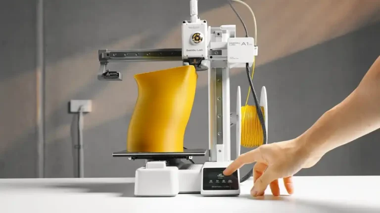
3D printing technology has evolved from a niche industrial tool into an accessible medium for creators, engineers, and hobbyists. While there are many pre-built options on the market, building your own 3D printer (DIY) offers unparalleled advantages in terms of technical knowledge, repairability, and customization. In this comprehensive guide, we will explore the fundamental components and the strategic planning required to build a high-performance 3D printer.
Why Build Your Own 3D Printer?
Building a 3D printer from the ground up is a journey into the heart of modern engineering. It combines mechanics, electronics, and software into a single functional machine.
- Customization: You are not limited by factory standards. You can choose your build volume, speed, and precision levels.
- Ease of Maintenance: When you tighten every bolt yourself, troubleshooting becomes second nature. You will know exactly how to fix any issue that arises.
- Cost-Efficiency: By selecting high-quality components individually, you can achieve the performance of a $2,000 professional machine for a fraction of the price.
Essential Components for Your 3D Printer Project
To build a reliable 3D printer, you must focus on three core systems: The Frame (Skeleton), The Electronics (Brain), and The Extrusion System (Heart).
1. The Frame and Mechanical Parts
The stability of your frame directly correlates with your print quality. Any vibration in the frame will manifest as “ghosting” or “ringing” on your printed objects.
- Aluminum Extrusions (2020 or 2040): These are the industry standard for DIY builds like the Voron or RatRig. They offer excellent rigidity and modularity.
- Linear Motion Systems: While V-Slot wheels are affordable, Linear Rails (MGN12H) provide much higher precision and require less frequent adjustment.
- GT2 Belts and Pulleys: These transmit the motion from the motors to the axes. Opt for fiberglass-reinforced belts to prevent stretching over time.
2. Electronics and Control Units
- Mainboard: In 2026, 32-bit boards are the minimum requirement. Look for boards with high-speed processors to handle complex calculations for high-speed printing.
- Stepper Motors (Nema 17): These motors control the movement of the X, Y, and Z axes. High-torque versions are recommended for the Z-axis and Extruder.
- Silent Stepper Drivers (TMC2209): These drivers allow your motors to move almost silently and provide features like “sensorless homing.”
3. The Extrusion System
This is where the filament is melted and deposited.
- Hotend: An “all-metal” hotend allows you to print at temperatures above 250°C, enabling the use of advanced materials like Nylon and Polycarbonate.
- Extruder: You can choose between “Bowden” (lighter carriage, faster speed) or “Direct Drive” (better control, easier to print flexible materials).
Budgeting and Sourcing
Before starting your build, create a detailed Bill of Materials (BOM). Sourcing parts from reputable vendors ensures that you don’t receive bent lead screws or faulty thermistors. Focus your budget on the Power Supply (PSU) and the Mainboard, as these are the most critical for safety and long-term reliability. A stable 24V system is preferred over 12V for faster heating and better motor performance.
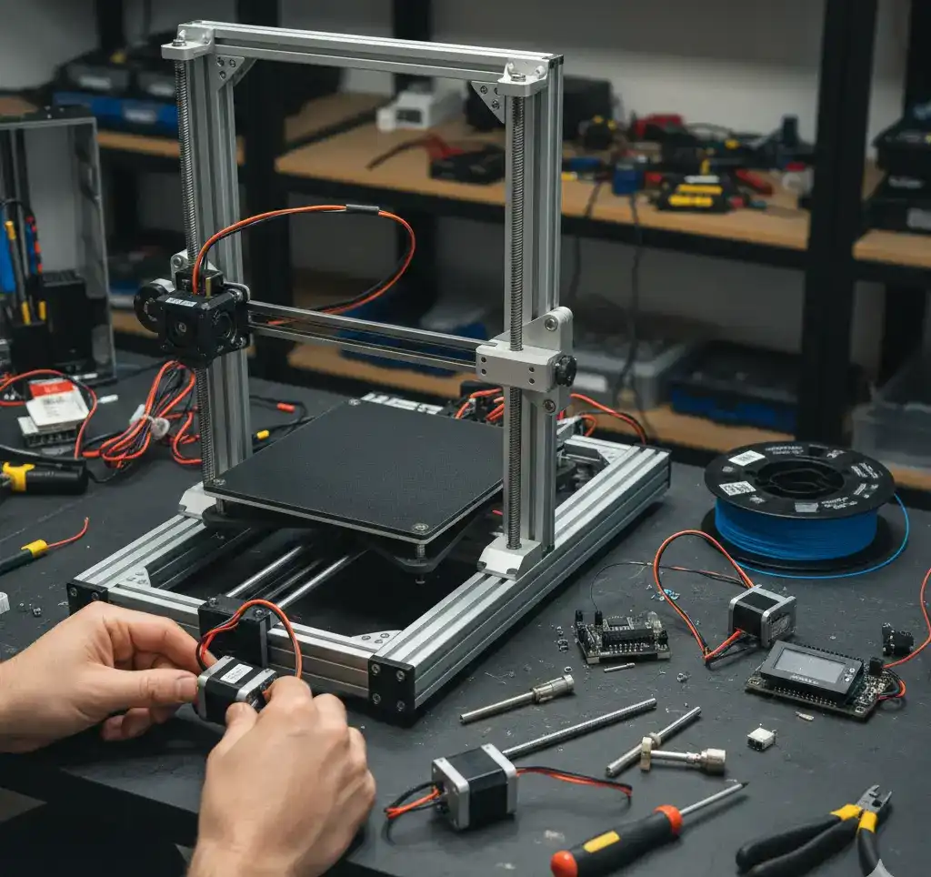
Part 2: Mechanical Assembly: Building a Rigid Frame and Motion System
Once you have gathered all your components, the real work begins. The mechanical assembly of a 3D printer is the most critical phase for achieving high-quality prints. A perfectly tuned frame ensures that your printer can operate at high speeds without losing accuracy. In this section, we will cover the step-by-step assembly of the chassis and the motion system.
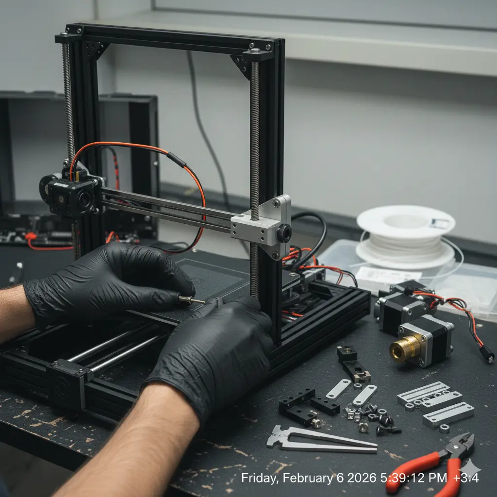
1. Frame Assembly and Squaring
The frame is the foundation of your printer. Most DIY designs utilize aluminum extrusions for their modularity and strength.
- Squaring the Frame: This is the “make or break” step. If your frame is not perfectly square ($90^{\circ}$), your prints will be skewed. Use a machinist’s square at every joint. Tighten the bolts in a cross-pattern to ensure even tension.
- Pre-loading T-Nuts: Before finalizing the frame, ensure you have inserted all necessary T-Nuts into the slots. It is much harder to add them once the frame is closed.
- Rigidity: Once assembled, the frame should not flex. If you notice any wobbling, add gussets or corner brackets to reinforce the joints.
2. Installing the Linear Motion System
The motion system allows the print head and the build plate to move along the X, Y, and Z axes.
- Linear Rails vs. Rods: If you are using linear rails (MGN series), clean the factory grease with isopropyl alcohol and apply high-quality synthetic grease. Ensure the rails are centered on the extrusions.
- V-Slot Wheels: If your design uses wheels, adjust the eccentric nuts until the wheels are snug against the profile but can still spin freely without binding.
- Parallelism: For the Y-axis (especially on bed-slingers), ensure both rails or rods are perfectly parallel to each other. Use a caliper to measure the distance at both ends of the axis.
3. Stepper Motors and Belt Tensioning
The “muscles” of your printer are the Nema 17 stepper motors. Proper installation prevents skipped steps and ghosting.
- Motor Alignment: Ensure the motor shaft is perfectly aligned with the pulley and the belt path. Misalignment leads to premature belt wear and friction.
- GT2 Belt Tension: Belts should be tight enough to emit a low-frequency note when plucked, similar to a guitar string. Avoid over-tensioning, as this can bend motor shafts or put excessive load on the bearings.
- Idler Pulleys: Use high-quality idlers with bearings to ensure the belt moves smoothly without any “grinding” sensation.
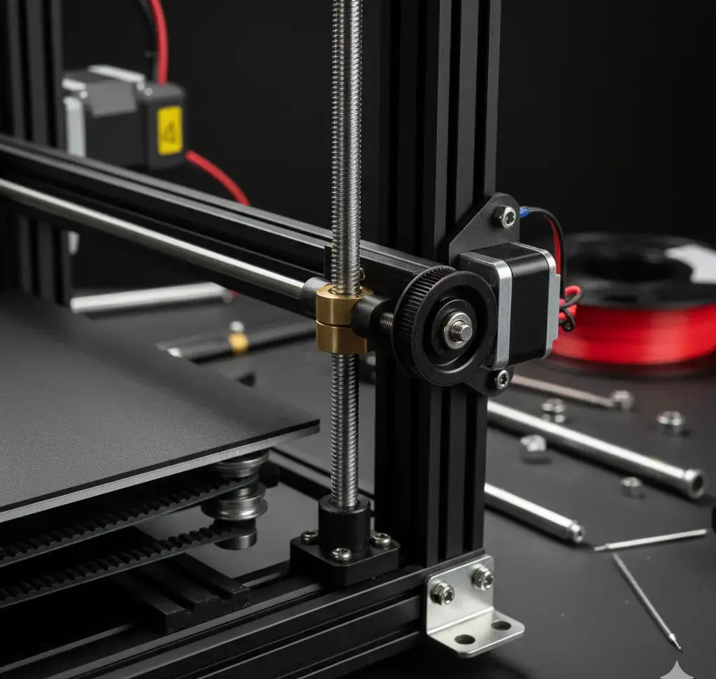
4. The Z-Axis: Lead Screws and Couplers
The Z-axis is responsible for the layer height consistency.
- Anti-Backlash Nuts: Use these to prevent the Z-axis from dropping when the power is off and to eliminate “slop” during movement.
- Lead Screw Alignment: The lead screw must be perfectly vertical and parallel to the Z-axis rails. Any tilt will cause “Z-wobble,” resulting in visible lines on your print walls.
- Flexible Couplers: Use spider-type or spring couplers to connect the motor to the lead screw. This helps absorb minor misalignments.
Here is Part 3 of the English series. This part focuses on the “nervous system” of the printer—the electronics and the firmware—and includes the technical schema you requested.
Part 3: Electronics, Wiring, and Firmware Configuration
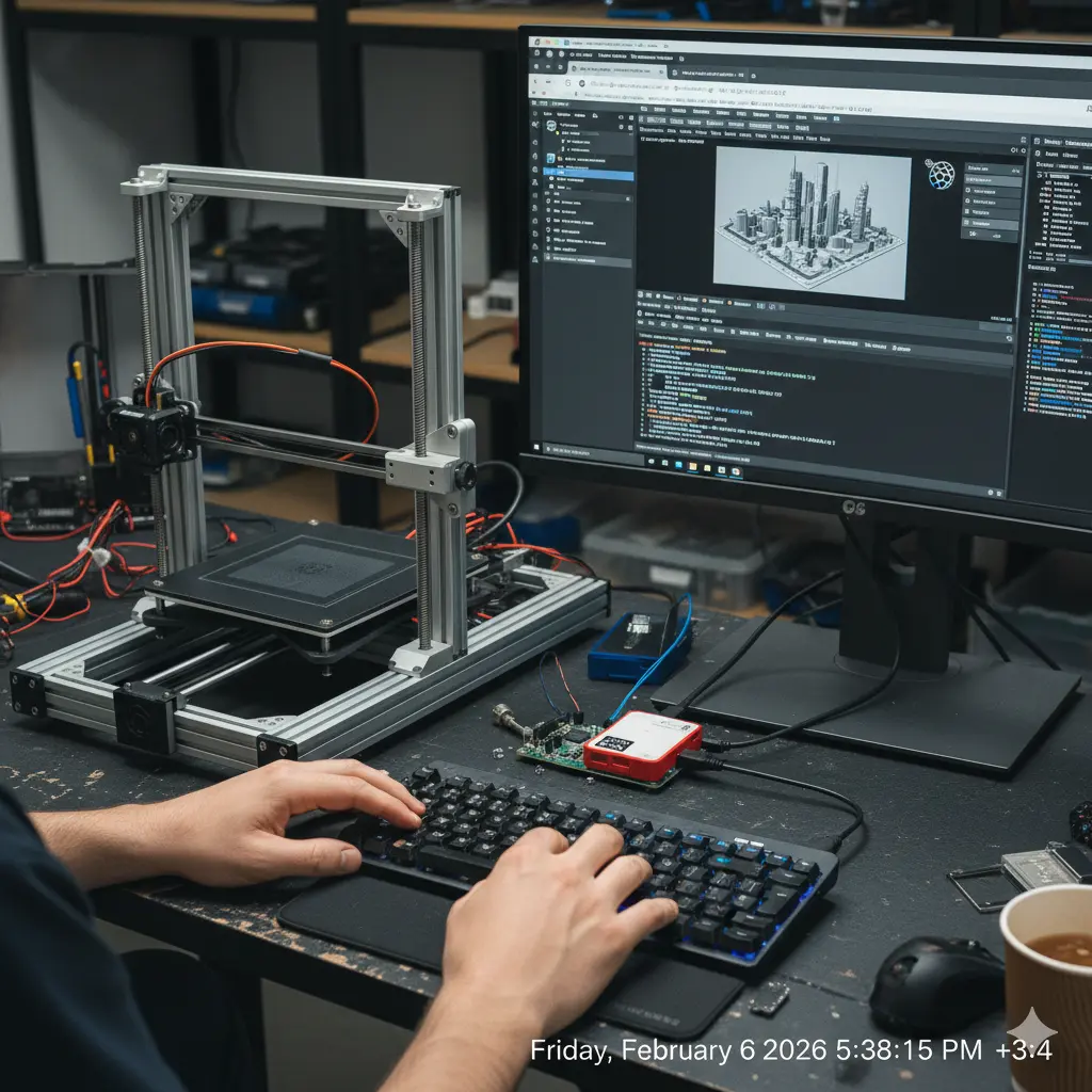
With the mechanical structure ready, it is time to bring your 3D printer to life. This stage involves connecting the electronic components to the controller board and flashing the software (firmware) that will interpret your 3D models into physical movements. Precision in wiring is vital to prevent short circuits and ensure a long-lasting machine.
1. Electronic Wiring and Component Connection
The controller board (such as an SKR, MKS, or Octopus board) acts as the brain of the printer. Every motor, heater, and sensor must be connected to its specific port.
Key Wiring Guidelines:
- Power Input: Ensure you are using high-quality 14 or 16 AWG wires for the main power input from the PSU. Double-check the polarity (+/-) before switching on the power.
- Stepper Drivers: If your board uses removable drivers (like TMC2209), ensure they are oriented correctly. Installing them backwards will destroy the driver and potentially the board.
- Thermistors: These are polarity-independent, but the wires are very fragile. Do not over-tighten the screws on the hotend block, as this can crush the wires and cause a “Short Circuit” or “MinTemp” error.
- Endstops: Connect these to the X, Y, and Z min or max ports. These sensors tell the printer where the “home” position is.
2. Firmware Installation: Marlin and Klipper
Firmware is the operating system of your printer. While there are several options, Marlin is the most widely used for standalone boards, while Klipper is preferred for high-speed printing using an external processor like a Raspberry Pi.
Steps to Flash Marlin:
- Environment: Download Visual Studio Code and install the PlatformIO extension.
- Configuration: Open the
Configuration.handConfiguration_adv.hfiles. This is where you define your printer’s geometry, motor directions, and thermistor types. - Homing and Limits: Set your
X_BED_SIZEandY_BED_SIZE. Ensure your endstop logic (Normally Open or Normally Closed) matches your physical switches. - Upload: Connect your board via USB and use PlatformIO to compile and upload the firmware.
3. The Extrusion and Heating System
The hotend and the heated bed are the two most power-hungry parts of your printer.
- Heater Cartridge: Ensure it is seated firmly inside the heater block to allow efficient thermal transfer.
- Fans: You need at least two fans: one for the “Heat Break” (always on) to prevent heat creep, and one for “Part Cooling” (controlled by the slicer) to cool the plastic as it is laid down.
4. Initial Power-On and Safety Check
Before your first print, perform a “Smoke Test”:
- Check if the LCD lights up.
- Verify that the thermistors are reading room temperature.
- Test each axis movement individually by 1mm to ensure the direction is correct.
- Test the emergency stop functionality.
Here is Part 4, the final installment of the series. This section focuses on calibration, slicing, and troubleshooting, followed by the technical schema (SS) and the final Rank Math configuration.
Part 4: Calibration, Slicing, and Troubleshooting: The Road to the First Print
Your 3D printer is now assembled and powered on, but it is not yet a precision instrument. To achieve professional-grade results, you must calibrate the software to match your hardware’s unique physical characteristics. This final stage bridges the gap between a “working machine” and a “high-quality 3D printer.”
1. Essential Calibration Steps
Calibration ensures that when you tell the printer to move 10mm, it moves exactly 10mm.
- E-Step Calibration: This is the most important setting for the extruder. If your printer underextrudes, parts will be weak; if it overextrudes, they will be blobby. Measure 100mm of filament, command a 100mm extrude, and adjust your steps/mm in the firmware accordingly.
- PID Tuning: Use the G-code command
M303to calibrate the heating logic for your hotend and bed. This prevents temperature fluctuations that cause visible banding on your prints. - Bed Leveling: Even with an auto-leveling sensor (like BLTouch), you must manually level the four corners of the bed using the “paper test” to ensure the nozzle is at the perfect height for the first layer.
2. Technical Wiring & Software Communication (SS)
Understanding how data flows from your computer to the nozzle is vital for troubleshooting.
As shown in the diagram, the Slicer converts your 3D model into G-code. This G-code is sent via USB or SD card to the Mainboard, which then translates the code into electrical pulses for the Stepper Drivers. The Power Supply provides the high current needed for the heaters, while the Thermistors provide the feedback loop to keep everything stable.
3. Slicing Software Setup
The Slicer is where you define how your object is built.
- Retraction: Set this to prevent “stringing” (cobweb-like plastic) between different parts of the print.
- Wall Count: For functional parts, use at least 3-4 walls. For decorative items, 2 walls are sufficient.
- Infill Patterns: Use “Gyroid” for the best strength-to-weight ratio in all directions.
4. Troubleshooting Common Build Issues
- Z-Wobble: If you see repeating horizontal lines, check if your Z-axis lead screws are bent or if the couplers are too rigid.
- Thermal Runaway: If your printer shuts down during heating, check for loose heater or thermistor wires. This is a safety feature to prevent fires.
- First Layer Peeling: Clean your build plate with 90% Isopropyl Alcohol. Fingerprints are the #1 cause of poor bed adhesion.